Nos activités
Intragaz opère les deux seuls sites d’entreposage de gaz naturel en gisement épuisé au Québec.
L’expérience aquise par Intragaz depuis près de trois décennies lui a permis de développer une grande connaissance du sous-sol québécois.
Intragaz opère les deux seuls sites d’entreposage de gaz naturel en gisement épuisé au Québec.
L’expérience aquise par Intragaz depuis près de trois décennies lui a permis de développer une grande connaissance du sous-sol québécois.
Intragaz a réalisé avec succès la conversion des deux seuls gisements épuisés de gaz naturel au Québec. Ces gisements sont situés dans deux horizons géologiques très différents : un site, très peu profond, dans le secteur de Pointe-du-Lac à Trois-Rivières et un autre, très profond, dans la municipalité de Saint-Flavien sur la rive sud du Saint-Laurent près de la ville de Québec.
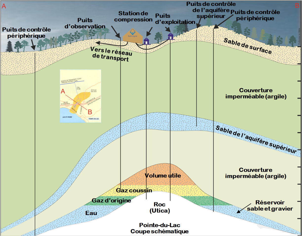
Le réservoir de Pointe-du-Lac est situé à environ 100 km au nord-est de Montréal, sur la rive nord du fleuve Saint-Laurent, à 12 km à l’ouest de Trois-Rivières. Le réservoir se présente comme une ellipse dont le grand axe est orienté NE/SO. Il s’agit d’un gisement de gaz épuisé en nappe aquifère. Il sert principalement pour le service de pointe (peak shaving). Il est raccordé par gazoduc au réseau de transport de Gazoduc TQM situé à 3 km au nord de la station de compression.
Le réservoir est constitué d’un sable non consolidé mis en place après l’avant-dernière période glaciaire, il y a environ 120 000 ans. Son épaisseur varie de quelques mètres à plus de 10 mètres. Il est situé à une profondeur variant entre 60 et 120 mètres seulement. La structure est causée par la présence d’un haut structural au niveau des formations géologiques du socle sur lequel s’est déposé un sable d’origine fluvio-glaciaire surmonté d’une argile imperméable qui sert de couverture. La perméabilité et la porosité exceptionnellement élevées du sable font que ce stockage est excellent pour le service de pointe.
Sa capacité quotidienne d’injection et de soutirage fait en sorte que l’on peut cycler son volume utile jusqu’à environ quatre fois dans une année. Il est reconnu comme l’un des moins profonds de tous les stockages en service. Sa faible pression à l’état naturel fait que les besoins de compression en soutirage sont élevés afin de pouvoir injecter dans le réseau gazier.
Voici la coupe schématique du site de Pointe-du-Lac, tel qu’il existe actuellement.
À cause de ses capacités d’injection et de soutirage, le stockage de Pointe-du-Lac est principalement utilisé pour la pointe d’hiver, mais peut également servir pour des volumes saisonniers. En voici sommairement les capacités.
| Volume utile | 37 600 103m3 | 1,3 Bcf |
| Débit maximal en soutirage | 2 000 103m3/j | 70,6 MMcf/j |
| Débit maximal en injection | 3 600 103m3/j | 127,1 MMcf/j |
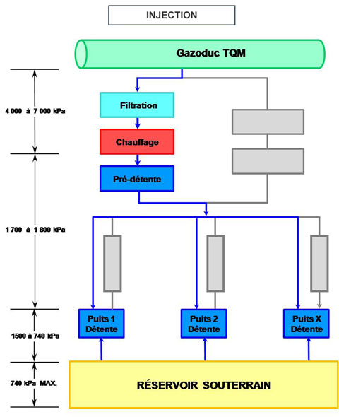
En raison de la faible profondeur (environ 70 m) du stockage, la pression dans le réservoir est faible (740 à 250 kPa) et notablement inférieure à celle du gazoduc de transport auquel il est raccordé (7 000 kPa). Il en résulte qu’à l’inverse de la plupart des sites de stockage exploités dans le monde, le gaz doit être comprimé lors du soutirage et, à l’inverse, détendu avant d’être injecté dans le réservoir.
L’injection débute avec une filtration et un réchauffage du gaz. Par la suite, le gaz est détendu une première fois à 1 500 kPa pour alimenter le réseau de collecte. Il est détendu une deuxième fois à chaque puits avant l’injection dans le gisement.

Au soutirage, l’eau libre entraînée est séparée du gaz par un unité de séparation à chaque puits. Le gaz humide provenant des puits est acheminé à la station et comprimé par quatre unités de compression, puis déshydraté pour être envoyé sur le réseau gazier.
Le site de stockage de Saint-Flavien, mis en service en 1998, se situe à environ 40 km au sud-ouest de la ville de Québec près de Laurier-Station, à quelque 10 km au sud de l’autoroute 20.
À la suite de divers travaux d’optimisation, le volume utile de Saint-Flavien est passé de 24 106m3 en 1998 à 120 106m3 en 2008.
Le réservoir de Saint-Flavien se trouve à une profondeur d’environ 1 500 mètres dans une zone géologique qui a été chevauchée lors de l’orogénèse des Appalaches, phase taconienne, survenue il y a 440 millions d’années. Il produit sur deux niveaux à partir d’une dolomie mise en place il y a environ 470 millions d’années et fait partie de la formation Beekmantown. Elle est recouverte de carbonate non poreux qui sert de couverture. L’épaisseur du réservoir varie entre 1 et 8 mètres avec une porosité de 2,5 % à plus de 10 %, mais avec une moyenne de 3 % à 5 %. La porosité est d’origine secondaire, c’est-à-dire que la porosité préexistante a été améliorée par l’apport de fluides hydrothermaux et la présence de fractures.
Le site de Saint-Flavien se présente comme suit. On peut voir de façon distincte les différents forages verticaux ou horizontaux effectués dans la structure géologique.
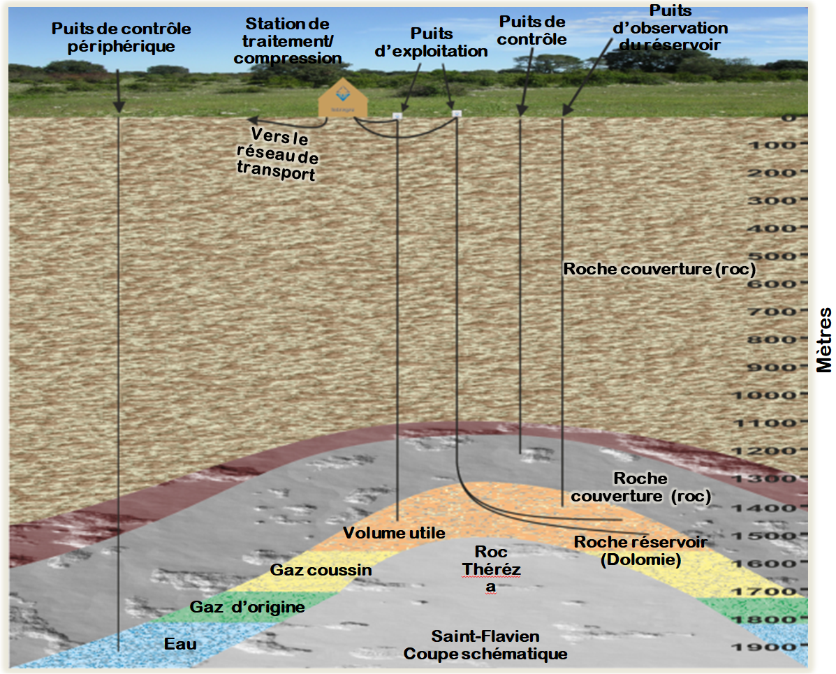

Jusqu’en 2023 le site de Saint-Flavien était exploité principalement comme un stockage saisonnier, car il peut soutenir pendant de longues périodes des débits élevés et nécessite une longue période de remplissage. À la suite de travaux d’optimisation réalisés en 2023 et la construction par Énergir d’une nouvelle conduite de 323,9 mm reliant le site au poste de Saint-Nicolas, le site de Saint-Flavien sera dorénavant utilisé également comme un outil de gestion de la pointe. En voici sommairement les capacités.
| Volume utile | 120 000 103m3 | 4,2 Bcf |
| Débit maximal en soutirage | 2 400 103m3/j | 84,8 MMcf/j |
| Débit maximal en injection | 900 103m3/j | 31,8 MMcf/j |
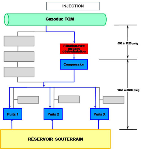
Lors de l’injection, le gaz provenant de Gazoduc TQM est d’abord filtré et comprimé par compresseur avant d’être acheminé, via un réseau de collecte, dans les divers puits. À chaque puits, le gaz est mesuré et injecté dans le réservoir.

Lors du soutirage, c’est la différence de pression entre le réservoir et le réseau gazier qui permet au gaz de sortir de chaque puits. Un système d’injection de méthanol localisé au puits assure la non-formation d’hydrates dans les conduites de gaz. Le gaz est acheminé dans le même réseau de collecte, réchauffé, détendu à la pression requise, et ensuite déshydraté avant sa réintroduction dans le gazoduc reliant le site au Gazoduc TQM. La compression est utilisée durant environ 60 jours pendant le soutirage.